| One method of consuming less energy is to
apply a voltage to the
solenoid coil to provide the necessary force to
pull the plunger in, then, when seated, drop the voltage down to a level
sufficient to maintain the plunger in a seated position. (See example in
Minimizing Unnecessary Energy Consumption
;
Voltage Reduction.)
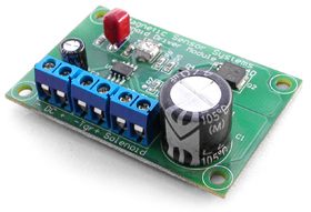
MSS' Pick and Hold Module is designed to apply an initial higher voltage to the coil for a pre-determined period of time and then drop the voltage to a pre-determined percentage of the initial value through pulse width modulation to avoid over heating the solenoid coil. The above voltage sequence will be applied to the coil when a voltage (2 to 40 VDC) is applied to the trigger. The trigger voltage can be a secondary voltage (external trigger) or the same voltage used for input voltage (internal trigger). This is particularly useful when a solenoid requiring a relatively large amount of power needs to be turned on and off with a low power trigger voltage such as a TTL compatible signal. |
|